Asset Details
Aerial Asset |
The available VBS2Combined Arms Aircraft platforms to be assigned for the mission |
|||||
Observer |
Select an Observer to observe the Strike mission |
|||||
Msn Type |
There are four types of Missions, which are ‘9Line’,’ ABBR 9 Line’, ‘Keyhole’, ‘Polar’
Note: |
|||||
Ctrl Type |
When a Strike mission is underway, the control type has to be specified. This does not affect the simulation, but it will be used for realistic training. Available control types are:
This information will be recorded in mission details for each and every task so that the user can go through each task and see with which control type category a particular task has been created. |
|||||
Fuel Limit |
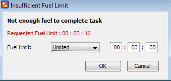
Limited: The Instructor can define how much fuel time an aircraft needs to reach the ‘First release point’ until refuel is needed. The time allocated cannot be empty or else the error message “Time should not be empty” will be shown as in Image 9d.2. The time allocated should be sufficient for the aircraft to fly to the ‘First Release point’ or else the error message “Insufficient Fuel Limit” as in Image 9d.3 will be displayed.
|
|||||
Aircraft |
Select the air platform to be assigned for the mission |
|||||
Initial Point/ Battle Position |
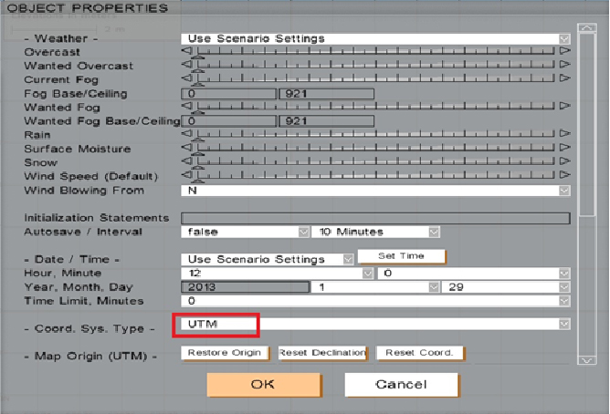
The starting grid location for the mission. The following reference grid types are available: MGRS ABBR, MGRS, UTM and REF PT. MGRS ABBR --> This is an eight digit reference value. This value can be retrieved by the VBS2 2D Map where it displays the horizontal (x axis) four digits and the vertical (y axis) four digits and combining them. (For instance if the x axis value ’5600’ and y axis value is ‘6600’ then the final grid value is‘56006600’) Note: In IP/ BP, ‘East/ West’, ‘North/ South’ and ‘Hold at Height’ variables are active only when Rotary wing selected UTM --> UTM coordinates of a position is a 14 digit value. This can be obtained from VBS2 2D map by following either of the methods below. Method1 :
Method 2:
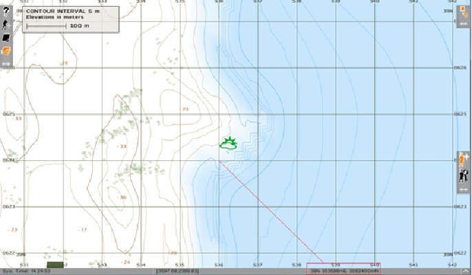
In the VBS2 2D Map view, select the exact target location by zoom In/Zoom out. The GPS Positioning Value will be displayed in the bottom of the map, as shown below.
If there is a missing coordinate value, add a 0 in front to replace the missing Grid value. Eg: 0359600 3063500 Note:
|
|||||
Heading |
The heading direction of the aircraft |
|||||
Distance |
Distance to target. |
|||||
Target Elevation |
The height to the target |
|||||
Target Description |
The Size, Type and Status of the target can be given as information to be viewed. |
|||||
Target Location |
The target grid location needs to be specified. The following reference grid types are available: MGRS ABBR, MGRS, UTM and REF PT. Note: Select Key Hole / Polar as the Start Location Refinement, only then will the Target Location “Same as Reference Point” check box be enabled. |
|||||
Mark Type |
This specifies the ability to provide a ‘Smoke’, ‘ILLUM’, ‘Designator’ or ‘IR’ round to appear at the vicinity of the target prior to the bomb hitting the target. Magic Mark contains five values:
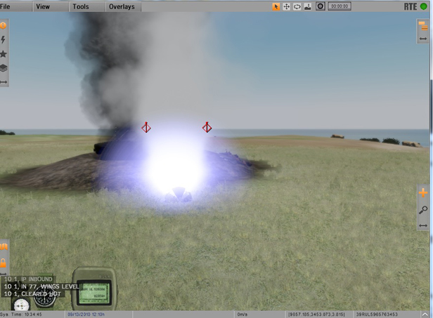
A laser designator is a laser light source which is used to designate a target. Laser designators provide targeting for laser guided bombs, missiles, or precision artillery munitions. VBS2Combined Arms is able to detect the designation of any player joined to the scenario as trainees. While the Trainee designates the target VBS2Combined Arms will pick the closest laser to a desired reference point .Normally this should be the target location. VBS2Combined Arms will detect any laser designation within radius of 800m from the initially given target.
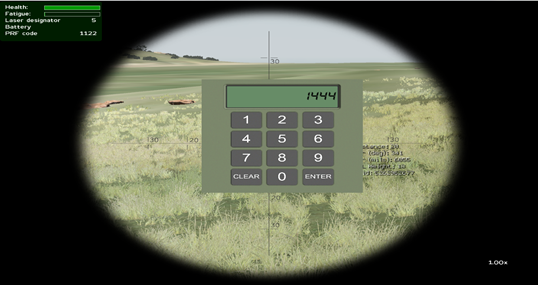
When the user selects Designator as the Mark Type at the task creation, a text box appears to enter the PRF code.
Note:
Valid PRF code must be in range of ‘1111-1788’ and only 1-8 digits can be used. If the user does not enter a PRF code, ‘1111’ is set as the default PRF code. This PRF code is common to all the aircrafts going for the attack and it will be displayed in HUD/POD/Manual Control/Pilot mode/Instructor POD views. When the projectile is released, the relevant PRF code along with the projectile will be displayed in Strike Projectile Analysis window. If the released weapon is not associated with a laser guided weapon, the PRF column will display ‘N/A’
Setting PRF to laser designator equipment
Weapons will be fired to the place which the observer is pointing the laser with the same PRF code given at the task creation. Initial target will be hit if same PRF code laser is not found in the particular area. Must know facts Scenario 1 Observer designates to the side of the target and the projectile doesn't detonate even if the target is achieved. The projectile is not firing a collision event with the surface area. (near miss). Scenario 2 Observer designates in such a way (with projectile release direction in consideration) so that the projectile shall definitely detonate. The projectile has sufficient surface area to accept as a collision event. If scenario 1 happens the projectile shall travel until it hits a surface. throughout that period of miss the TTT (count down) shall be 0. Note:
The laser designating point can vary within 15 degrees to the given target. Guided arms such as 70mm/127mm Aerial Rockets, Hellfire, TOW, Maverick and Guided Bombs 250/500/1000/2000 lbs. should be used as weaponry types. |
|||||
Nearest Friendlies |
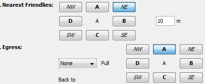
Details of the Friendlies near the target in a particular direction and distance is given here. |
|||||
Egress |
If ‘Left’ or ‘Right’ selected as the Egress direction, then the aircraft may turn to that direction after the last weapon is fired. But if ‘None’ is selected then the aircraft will turn to the optimal direction in order to get the user specified egress direction and then fly around 2km (2000m) along that direction in a straight line path. |

